

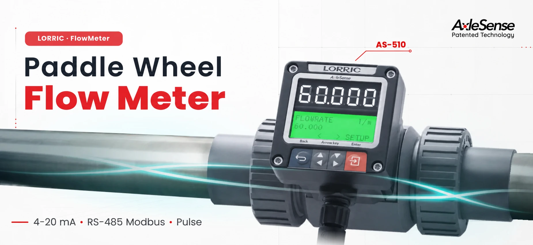
Paddle Wheel Flowmeter
LORRIC AS510 SERIES
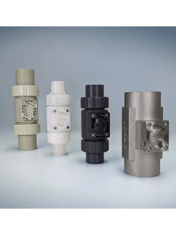
AS510 Paddle Wheel Flow Meter Models
Outputs available on all models
4–20 mA RS-485 Modbus Pulse
CODE
IMAGE
CONNECTION
FLOW RANGE
BODY MATERIAL OPTIONS
CODE
FP-AS510-FP-P015 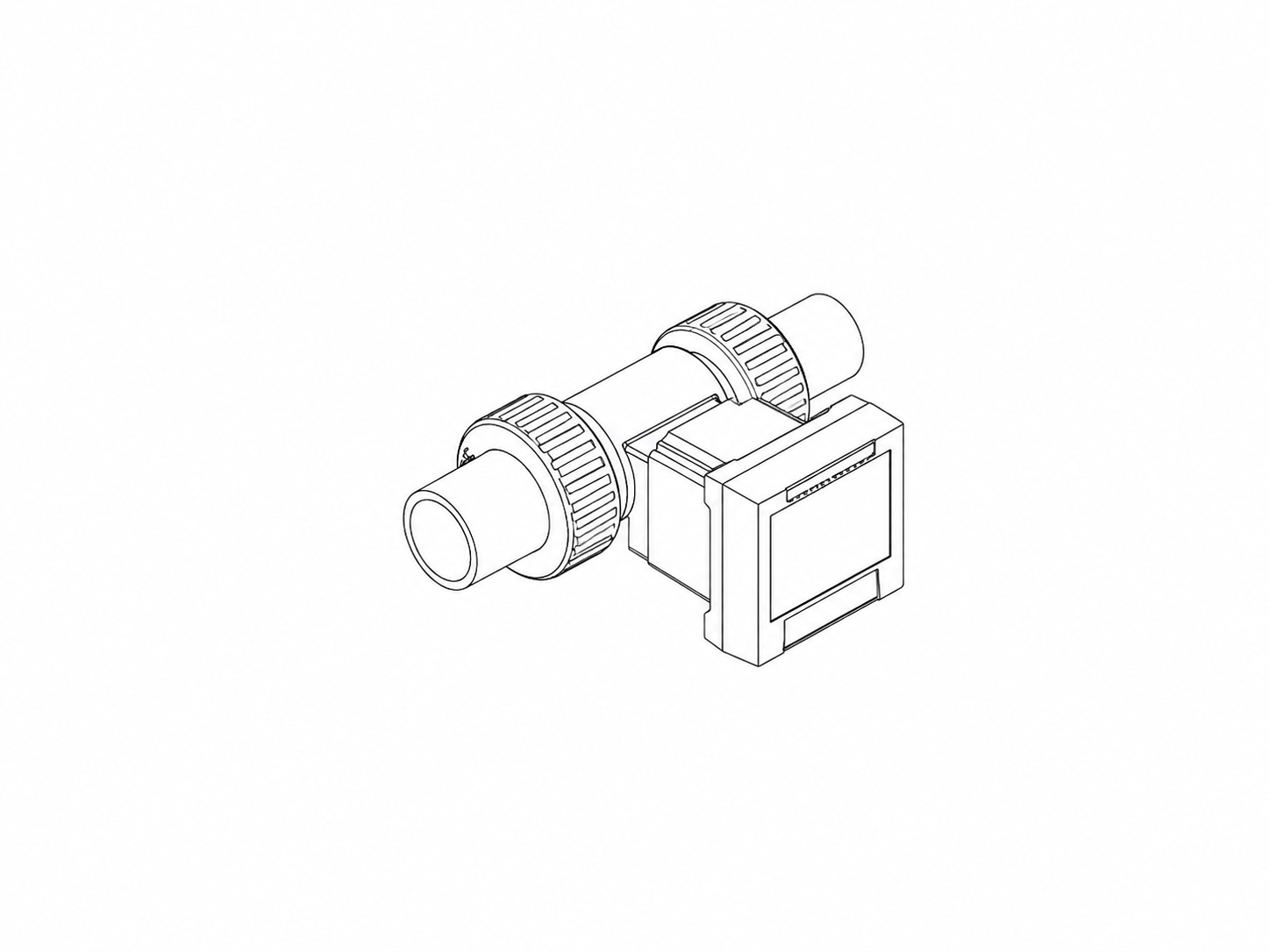
CONNECTION
DN15
1/2"
FLOW RANGE
1.8–120.6
L/min
BODY MATERIAL OPTIONS
UPVC (stock model) · PPH · PVDF · SS316 CODE
FP-AS510-FP-P020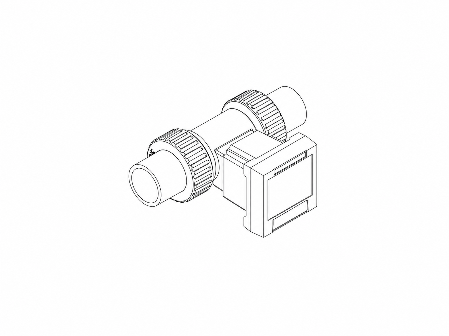
CONNECTION
DN20
3/4"
FLOW RANGE
2.9–188.5
L/min
BODY MATERIAL OPTIONS
UPVC (stock model) · PPH · PVDF · SS316 CODE
FP-AS510-FP-P025
CONNECTION
DN25
1"
FLOW RANGE
4.4–294.5
L/min
BODY MATERIAL OPTIONS
UPVC (stock model) · PPH · PVDF · SS316 CODE
FP-AS510-FP-P032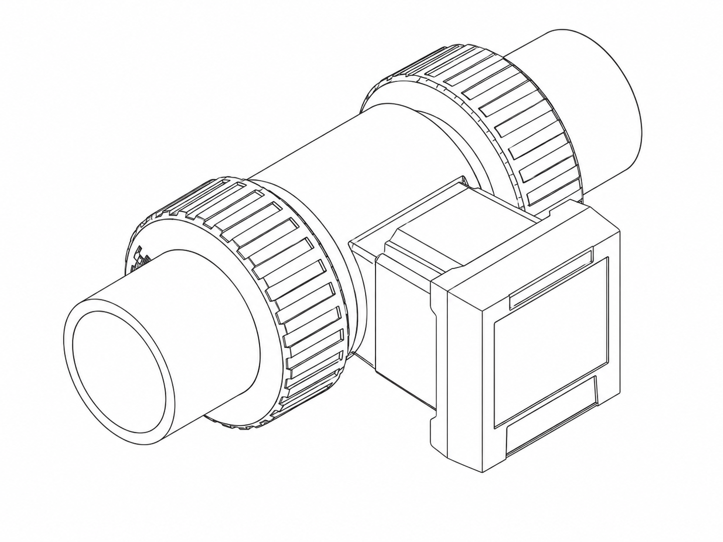
CONNECTION
DN32
1-1/4"
FLOW RANGE
6.8–452.9
L/min
BODY MATERIAL OPTIONS
UPVC (stock model) · PPH · PVDF · SS316 CODE
FP-AS510-FP-P040CONNECTION
DN40
1-1/2"
FLOW RANGE
11.3–754.0
L/min
BODY MATERIAL OPTIONS
UPVC (stock model) · PPH · PVDF · SS316 CODE
FP-AS510-FP-P050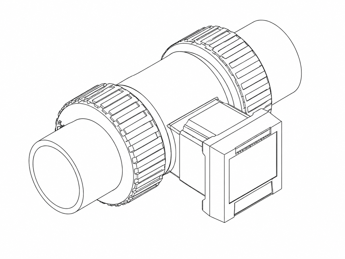
CONNECTION
DN50
2"
FLOW RANGE
18.4–1225.7
L/min
BODY MATERIAL OPTIONS
UPVC (stock model) · PPH · PVDF · SS316 CODE
FP-AS510-FP-P065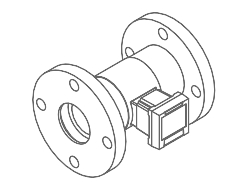
CONNECTION
DN65
2-1/2"
Flanged
FLOW RANGE
32.7–2179.0
L/min
BODY MATERIAL OPTIONS
UPVC (stock model) · PPH · PVDF When selecting a model, the flow range, pipe diameter, fluid properties, body material and process temperature should be evaluated together.
FLOW MEASUREMENT TECHNOLOGY
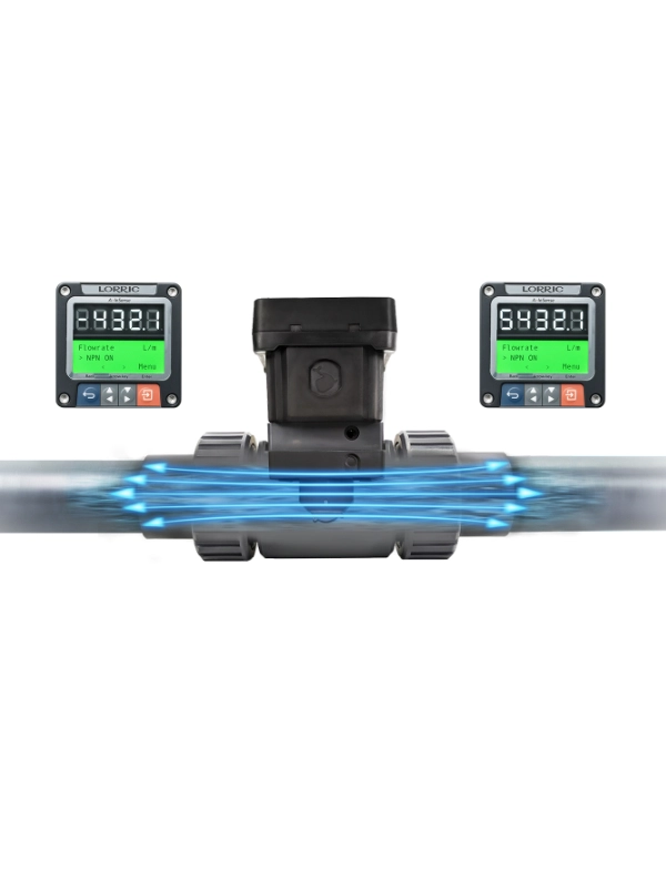
Operating Principle and AxelSense Technology


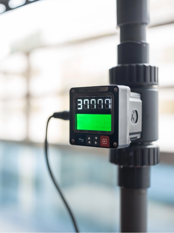
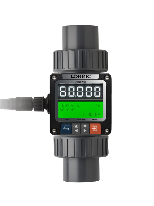
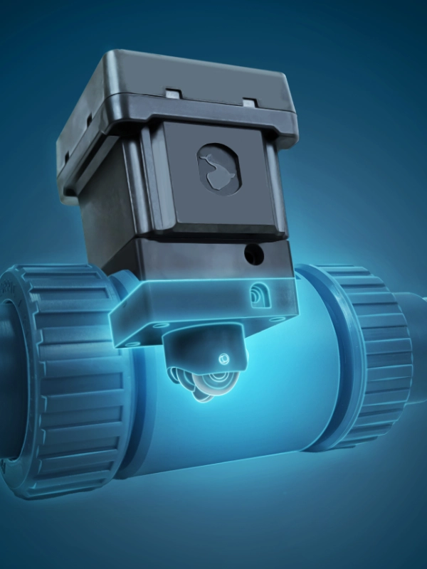
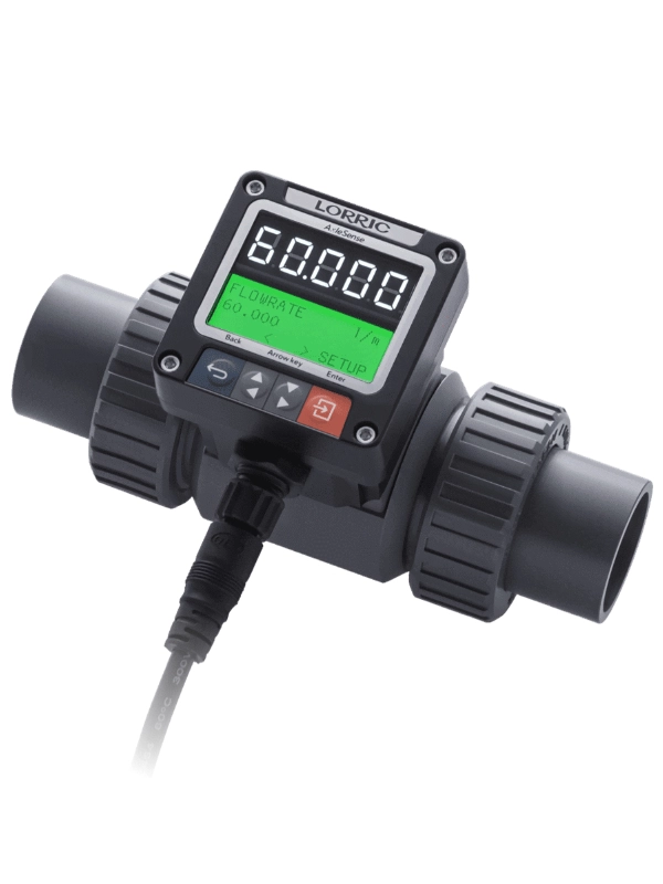
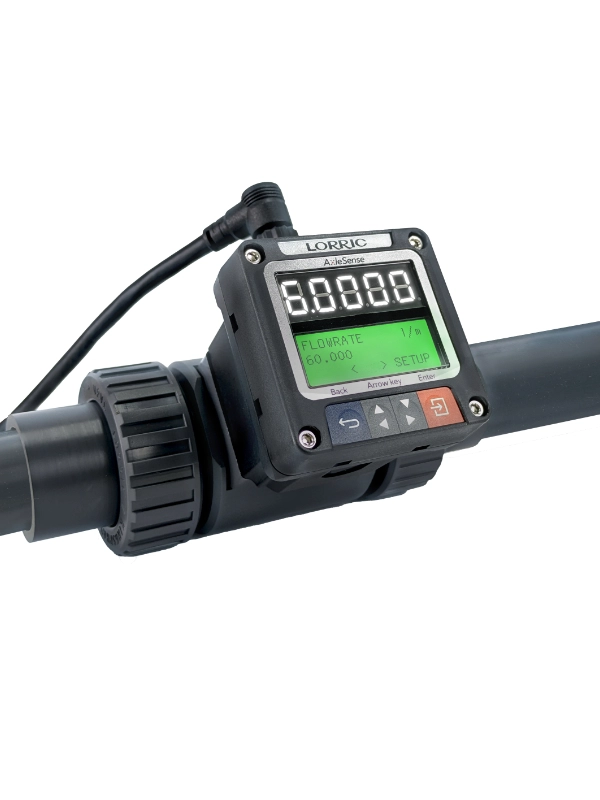
LORRIC AS510
Technical Specifications
MEASUREMENT & PROCESS
Compatible Fluids
Various liquids · Foreign matter / impurity content < 1%
Maximum Fluid Viscosity
300 cSt
The device is factory-calibrated using water at normal temperature. Fluids with a viscosity different from water may affect the calibration values and minimum / maximum flow limits.
Fluid Temperature
UPVC 0…+50 °C PPH 0…+90 °C PVDF −15…+100 °C SS316L −20…+100 °C
Operating temperature values are provided as a reference for material selection. Final material selection should be made according to the fluid and process conditions.
Operating Ambient Temperature
−10…+60 °C
Velocity Measurement Range
±0.3…10 m/s Extended: ±0.15…10 m/s
The minimum measurement value may vary slightly depending on the model and the flow profile inside the pipe.
Flow Measurement Range
The flow measurement range varies depending on the selected pipe diameter and AS510 model. Current model-specific measurement ranges are listed in the AS510 Models table above.
Measurement Accuracy
±2.5% OR
This value is specified by LORRIC using clean water under controlled laboratory conditions at 25 °C. Actual process conditions may affect measurement error.
Linearity
±0.5% FS (>0.3 m/s)
Repeatability
±0.4%
Units
liter, m³, meter, s, min, hour, day, feet³, UK gallon, US gallon
Display Update Time
0.5 s / 1 s
ELECTRICAL & COMMUNICATION
Power Supply
12…36 VDC · 100 mA
Output Signals
4–20 mA · 16 bit RS-485 · Modbus RTU Pulse / Optocoupler
Cable & Connector
M12 · 8-pin
A 2 m connection cable is included in the package.
A 2 m connection cable is included in the package.
Electrical Protection
Reverse Polarity Protection Power Supply Surge Protection
DEVICE & PROTECTION
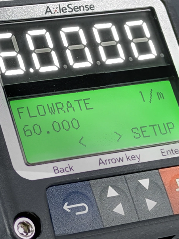
Display
Dual Display
Large 5-digit LED · 16×3 LCD with 3-color backlight
Large 5-digit LED · 16×3 LCD with 3-color backlight
Display Resolution
Maximum 0.0001
Totalizer & Cumulative Data
Positive Flow Negative Flow Net Flow
When a calendar battery is used, daily total volume values for the previous 14 days can be stored.
Protection Rating
IP66
You can view the LORRIC AS510 interactive user manual below. Use the document menu to navigate between sections.
The manual is displayed from LORRIC's official online documentation system.
The correct installation position of the LORRIC AS510 Paddle Wheel Flow Meter is important for stable and reliable flow measurement. It is recommended that the pipe remain completely filled with liquid, sufficient straight pipe lengths are provided, and the flow meter is installed at an appropriate distance from components that may disturb the flow profile.
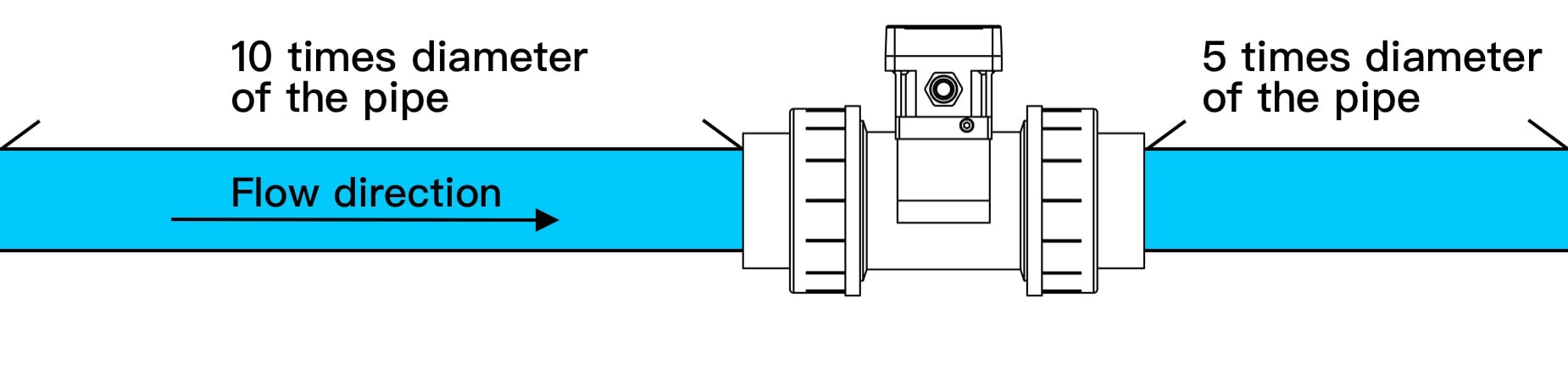
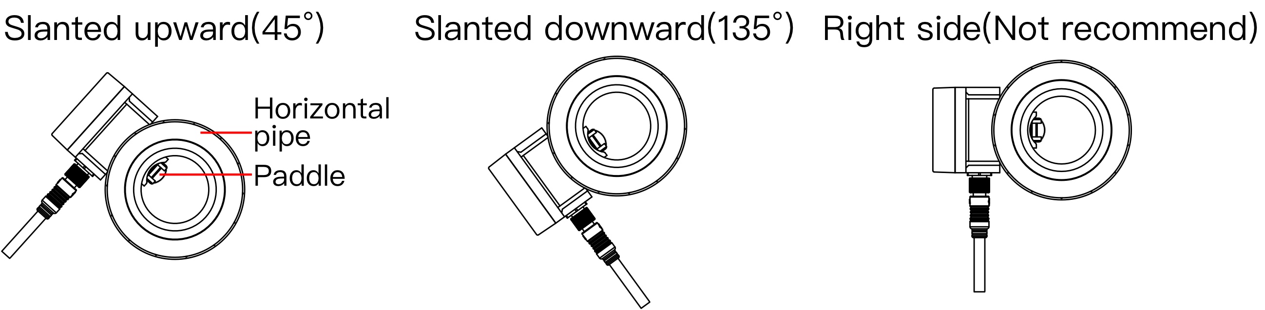
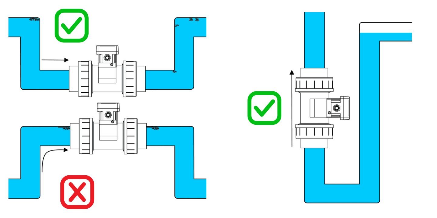
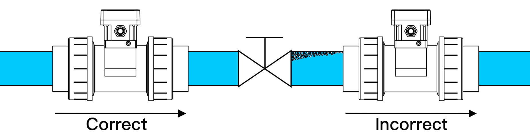
Installation Note: Pipe diameter, fluid properties, solid particle content, process pressure, temperature and the site piping layout should be evaluated together. If particles or sediment that could affect paddle movement are present in the fluid, the use of suitable filtration on the inlet line should be considered.
The LORRIC AS510 electrical connection is made through an M12 8-pin connector. The device supports 12–36 VDC power supply, 4–20 mA analog output, RS-485 Modbus communication, and OCT / Pulse output connections. It is recommended to insulate unused cable ends and perform all wiring while the device is powered off.


Connection Note: Before making any electrical connections, it is recommended to disconnect power from the device and insulate unused cable ends against short circuits. The input / output configuration of the PLC, controller, or higher-level system used in the application should also be taken into consideration.
Now you can download the following software suitable for you. After clicking the button, the download link of the software will be sent to your e-mail address.